Note
Last update 03/05/2021
Organization of SuperflexPy
SuperflexPy is designed to operate at multiple levels of complexity, from a single reservoir to a complex river network.
All SuperflexPy components, namely elements, units, nodes, network, are designed to operate alone or as part of other components. For this reason, all components have methods that enable the execution of basic functionality (e.g. parameter handling) at all levels. For example, consider a unit that contains multiple elements. The unit will then provide the functionality for setting the parameter values for its elements.
Note that, programmatically, SuperflexPy component types are classes, and the actual model components are then class instances (objects).
We will first describe each component type in specific detail, and then highlight some Generalities that apply to all components.
Elements
Elements represent the basic level of the SuperflexPy. Conceptually, SuperflexPy uses the following elements: reservoirs, lag functions, and connections. Elements can be used to represent a complete model structure, or combined together to form one or more Unit.
Depending on their type, conceptual elements can have parameters and/or states, can handle multiple fluxes as inputs and/or as outputs, can be designed to operate with one or more elements upstream or downstream, can be controlled by differential equations or by a convolution operations, etc.
Programmatically, the conceptual elements can be implemented by extending the following classes:
BaseElement: for elements without states and parameters (e.g., junctions);StateElement: for elements with states but without parameters;ParameterizedElement: for elements with parameters but without states (e.g., junctions);StateParameterizedElement: for elements with states and parameters (e.g., reservoirs and lag functions).
For example, consider the conceptual element “junction”, which sums the fluxes coming
from multiple elements upstream without needing states or parameters. This element can be
built by extending the class BaseElement to implement the method that
sums the fluxes.
To facilitate usage, SuperflexPy provides a set of “pre-packaged” classes that already implement already most of the functionality needed to specify reservoirs, lag functions, and connections. The next sections focus on these classes.
Reservoirs
A reservoir is a storage element described by the differential equation (or, more generally, a system of differential equations)
where \(\mathbf{S}\) represents the internal states of the reservoir, \(\mathbf{I}\) represents the sum of all input fluxes, \(\mathbf{O}\) represents the sum of all output fluxes, and \(\mathbf{\theta}\) represents the parameters that control the behavior of the reservoir. In most conceptual models, reservoir elements have a single state variable (representing water storage), however multiple state variables can be accommodated when necessary (e.g., to represent transport).
SuperflexPy provides the class ODEsElement that contains all the logic
needed to represent an element controlled by a differential equation. The user needs
only to specify the equations defining input and output fluxes.
The differential equation is solved numerically, though analytical solutions could be possible. The choice of solution method (e.g. the implicit Euler scheme) is made by the user when initializing the reservoir element.
SuperflexPy provides several “numerical approximators” to solve decoupled ODEs,
including the implicit and the explicit Euler schemes. The user can either
employ the numerical routines provided by the framework, or implement the
interface necessary to use an external solver (e.g. from scipy), which
may be needed when the numerical problem becomes more complex (e.g. coupled
differential equations). For more information about the numerical solver refer
to the page Numerical implementation.
Lag functions
A lag function is an element that applies a delay to the incoming fluxes. In mathematical terms, the lag function represents a convolution of the incoming fluxes with a weight function. Here, the convolution is implemented by distributing the fluxes at a given time step into the subsequent time steps, according to a weight array. The same procedure is then repeated over multiple time steps, adding together the contributions originating from the preceding time steps.
SuperflexPy provides the class LagElement that implements all the
methods needed to represent a lag function. The user only needs to define the
weight array.
Connections
Connection elements are used to link together multiple elements when building a unit.
SuperflexPy provides several types of connection elements. For example, a
Splitter is used to split the output flux from a single upstream element
and distribute the respective portions to multiple downstream elements.
Conversely, a Junction is used to collect the output fluxes from
multiple upstream elements and feed them into a single downstream element.
Connection elements are designed to operate with an arbitrarily number of fluxes
and upstream/downstream elements.
Splitter
A Splitter is an element that receives the outputs of a single upstream
element and distributes them to several downstream elements.
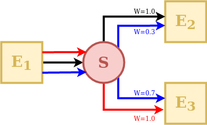
The behavior of a splitter in SuperflexPy is controlled by two matrices: “direction” and “weight”. The direction matrix specifies which input fluxes contribute (even fractionally) to the downstream elements and in which order. The weight matrix defines the proportion of each of the input fluxes that goes into each the downstream element.
In the illustration schematic, element S receives 3 input fluxes, which are coloured and indexed according to their order: red (index 0), black (index 1), and blue (index 2). Element E2 receives the black flux as its first input (index 0), the blue flux as its second input (index 1), and does not receive any portion of the third flux. Element E3 receives the blue flux as its first input (index 0), the red flux as its second input (index 1), and does not receive any portion of the black flux.
This information is represented by the direction matrix \(\mathbf{D}\) as follows:
The direction matrix is a 2D matrix with as many columns as the number of fluxes and as many rows as the number of downstream elements. The row index refers to a downstream element (in this case the first row refers to element E2, and the second row to element E3). The column index refers to the input fluxes received by to the downstream element. Note that care must be taken when indexing the elements and fluxes to correctly reflect the intended model structure.
The values of \(\mathbf{D}\) can be an integer referring to the index of the
input flux to the splitter S, or None if an input flux to the splitter S
does not reach a downstream element.
As such, the direction matrix can be used to select the fluxes and change the order in which they are transmitted to downstream elements.
Next, we consider the weight matrix \(\mathbf{W}\), which describes the fraction of each flux directed to each downstream element. The red flux is taken entirely by element E3, the black flux is taken entirely by element E2, and the blue flux is split at 30% to E2 and 70% to E3. This information is represented as follows:
The weight matrix has the same shape as the direction matrix. The row index refers to the downstream element, in the same order as in the direction matrix \(\mathbf{D}\), whereas the column index refers to the input flux to the splitter S.
The elements of \(\mathbf{W}\) represent the fraction of each input flux received by the splitter S and directed to the downstream element. In the example, the first downstream element (first row of the matrix \(\mathbf{W}\)) receives 0% of the first (red) flux, 100% of the second (black) flux, and 30% of the third (blue) flux.
Note that the columns of the weight matrix should sum up to 1 to ensure conservation of mass.
Junction
A Junction is an element that receives the outputs of several upstream
elements and directs them into a single downstream element.
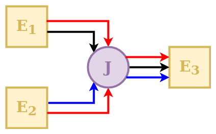
The behavior of a junction in SuperflexPy is controlled by a direction matrix, which defines how the incoming fluxes are to be combined (summed) to feed the downstream element.
In the schematic, element E3 receives 3 input fluxes, which are indexed based on their order: red (index 0), black (index 1), and blue (index 2). The red flux comes from both upstream elements (index 0 and 1, respectively); the black flux comes only from element E1 (index 1); the blue flux comes only from element E2 (index 2). This information is represented by the direction matrix \(\mathbf{D}\) as follows:
The direction matrix is a 2D matrix that has as many rows as the number of fluxes and as many columns as number of upstream elements. The row index refers to the flux (in this case the first row refers to the red flux, the second row to the black flux, and the third row to the blue flux). The column index refers to the upstream element input flux to the junction (in this case the first column refers to element E1, the second column to element E2).
The value of the matrix element can be an integer referring to the index of the
input flux to junction J coming from the specific upstream element, or
None if an input flux to junction J does not come from the upstream element.
Linker
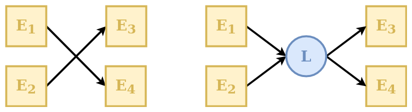
A Linker is an element that can be used to connect multiple elements
upstream to multiple elements downstream without mixing fluxes.
Linkers are useful in SuperflexPy because the structure of the unit is defined as an ordered list of elements (see Unit). This means that if we want to connect the first element of a layer to the second element of the following layer (e.g., direct the output from upstream element E1 to downstream element E4, in the example above) we have to insert an additional intermediate layer with a linker that directs the fluxes to the correct downstream element. Further details on the organization of the units in layers are presented in section Unit.
Transparent
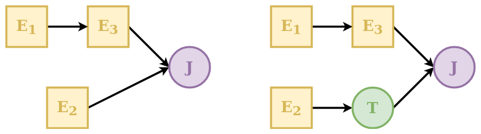
A transparent element is an element that returns, as output, the same fluxes that it receives as input. This element is needed to fill “gaps” in the structure defining a unit. See Unit for further details. An example is shown in the schematic above where the transparent element is used to make the two rows have the same number of elements.
Unit
A unit is a collection of multiple connected elements. The unit can be used either alone, when intended to represent a lumped catchment model, or as part of a Node, to create a semi-distributed model.
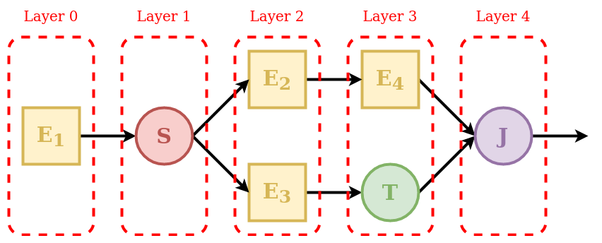
As shown in the schematic, elements are organized as a succession of layers, from left (upstream) to right (downstream).
The first and last layers must contain only a single element, since the inputs of the unit are “given” to the first element and the outputs of the unit are “taken” from the last element.
The order of elements inside each layer defines how they are connected: the first element of a layer (e.g. element E2 in the schematic) will transfer its outputs to the first element of the downstream layer (e.g. element E4); the second element of a layer (e.g. element E3) will transfer its outputs to the second element of the downstream layer (e.g. element T), and so on.
When the output of an element is split between multiple downstream elements an additional intermediate layer with a splitter is needed. For example, element E1 is intended to provide its outputs to elements E2 and E3. In this case the splitter S has two downstream elements (E2 and E3); the framework will route the first group of outputs of the splitter to element E2 and the second group of outputs to element E3.
Whenever there is a “gap” in the structure, a transparent element should be used to fill the gap. In the example, the output of element E3 is combined with the output of element E4. Since these elements belong to different layers, making this connection directly would create a gap in Layer 3. This problem is solved by specifying a transparent element in Layer 3, i.e., in the same layer as element E4.
Finally, since the unit must have a single element in its last layer, the outputs of elements E4 and T must be collected using the junction J.
Each element is aware of its expected number of upstream and downstream elements. For example, a reservoir must have a single upstream element and a single downstream element, a splitter must have a single upstream element and potentially multiple downstream elements, and so on. A unit is valid only if all layers connect to each other using the expected number of elements. In the example, Layer 1 must have two downstream elements that is consistent with the configuration of Layer 2.
Elements are copied into the unit. This means that an element that belongs to a unit is completely independent from the originally defined element and from any other copy of the same element in other units. This SuperflexPy design choice ensures that changes to the state or to the parameters of an element within a given unit will not affect any element outside of that unit. The code below illustrates this behavior:
1e1 = Element(parameters={'p1': 0.1}, states={'S': 10.0})
2
3u1 = Unit([e1])
4u2 = Unit([e1])
5
6e1.set_parameters({'e1_p1': 0.2})
7u1.set_parameters({'u1_e1_p1': 0.3})
8u2.set_parameters({'u2_e1_p1': 0.4})
In the code, element e1 is included in units u1 and u2.
In lines 6-8 the value of parameter p1 of element e1 is changed
at the element level and at the unit level. Since elements are copied into a
unit, these changes apply to three different elements (in the sense of different
Python objects in memory), the “originally defined” e1 and the copies of
e1 in u1 and u2.
For more information on how to define a unit structure in SuperflexPy, refer to the page Application: implementation of existing conceptual models, where the framework is used to reproduce some existing lumped models.
Node
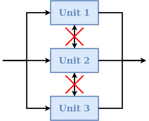
A node is a collection of multiple units assumed to operate in parallel. In the context of semi-distributed models, a node represents a single catchment and the units represent multiple landscape elements (areas) within the catchment. A node can be run either alone or as part of a bigger Network.
The default behavior of nodes is that parameters are shared between elements of the same unit, even if that unit belongs to multiple nodes. This SuperflexPy design choice is motivated by the unit being intended to represent areas that have the same hydrological response. The idea is that the hydrological response is controlled by the parameters, and therefore elements of the same unit (e.g. HRU) belonging to multiple nodes should have the same parameter values.
On the other hand, each node has its own states that are tracked separately from the states of other nodes. In particular, when multiple nodes that share the same parameter values receive different inputs (e.g., rainfall), their states will evolve differently. This SuperflexPy design choice supports the most common use of nodes, which is the discretisation of a catchment into potentially overlapping HRUs and subcatchments. Parameters are then assumed constant within HRUs (units), and inputs are assumed to be constant within subcatchments (nodes).
In term of SuperflexPy code, this behavior is achieved by (1) copying the states of the elements belonging to the unit when this unit becomes part of a node; (2) sharing, rather than copying, the parameter values. This means that changes to the parameter values of an element within a node will affect the parameter values of that elements of all other nodes that share the same unit. In contrast, changes to the states will be node-specific.
This default behavior can be changed by setting shared_parameters=False
at the initialization of the node. In this case, all parameters become
node-specific, with no sharing of parameter values even within the same unit.
Refer to the section Simple semi-distributed model for details on how to incorporate units into nodes.
Routing
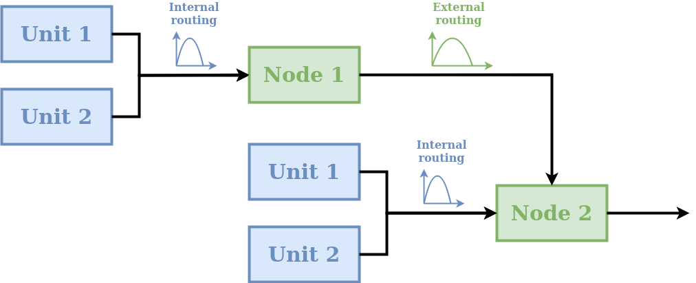
A node can include routing functions that delay the fluxes. As shown in the schematic, two types of routing are possible:
internal routing;
external routing.
A typical usage of these routing functions in semi-distributed hydrological modelling is as follows. Internal routing is used to represent delays associated with the routing of fluxes across the catchment towards the river network. External routing is used to represent delays associated with the routing of fluxes within the river network, i.e., from the outlets of the given node to the inlet of the downstream node.
More generally, routing functions can be used for representing any type of delay between the units and the node, as well as delays between nodes.
In the default implementation of a node in SuperflexPy, the two routing functions simply return their input (i.e. no delay is applied). The user can implement a different behavior, e.g., see section Adding routing to a node.
Network
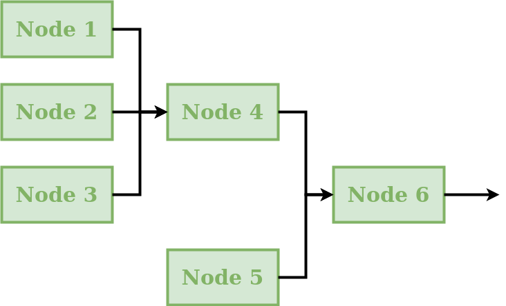
A network connects multiple nodes into a tree structure, and is typically intended to develop a distributed model that generates predictions at internal subcatchment locations (e.g. to represent a “nested” catchment setup).
The connectivity of the network is defined by assigning to each node the information about its downstream node. The network will then compute the node output fluxes, starting from the inlets and then moving downstream, calculating the outflows of the remaining nodes and routing the fluxes towards the outlet.
The network is the only component of SuperflexPy that does not have the
set_input method (see Generalities), because inputs are assumed
to be node-specific and hence have to be assigned to each node within the
network.
A node is inserted (rather than copied) into the network. In other words, we initialize a node object and then insert it into the network. This node can then be configured either directly or through the network. Any changes occurring within the node as part of the network affect also the originally defined node (because they are the same Python object).
The output of the network is a dictionary that contains the output of all nodes within the network.
Generalities
Common methods
All components share the following methods.
Parameters and states: each component has its own parameters and/or states with unique identifiers. Each component of SuperflexPy has methods to set and get the states and parameters of the component itself as well as the states and parameters of its contained components:
set_parameters: change the current parameter valuesget_parameters: get the current parameter valuesget_parameters_name: get the identifiers of the parametersset_states: change the current state valuesget_states: get the current state valueget_states_name: get the identifiers of the statesreset_states: reset the states to their initialization value
Time step: as common in hydrological modeling, inputs and outputs are assumed to have the same time resolution, i.e., the input and output data must share the same time stamps. There is no requirement for timestamps to be uniformly spaced, meaning that the time series can have irregular time step sizes. In SuperflexPy, all components that require the definition of a time step (e.g. reservoirs described by a differential equation) contain methods that set and get the time step size. In case of non-uniform time resolution, an array of time steps needs to be provided by the user.
set_timestep: set the time step used in the model. All components at a higher level (e.g. units) have this method; when called, it applies the change to all elements within the component;get_timestep: returns the time step size used in the model.
Inputs and outputs: all components have functionalities to receive inputs and generate outputs.
set_input: set the component inputs; inputs can be fluxes (e.g., precipitation) or other relevant variables (e.g., temperature influencing the behavior of a snow element).get_output: run the component (and all components contained in it) and return the output fluxes.
Component identifiers
In SuperflexPy, ll parameters, states, and components (except for the network)
are identified using an identifier string assigned by the user. The identifier
string can have an arbitrary length, with the only restriction being that it cannot
contain the underscore _, as this is a special character used internally
by SuperflexPy.
When an element is inserted into a unit or when the unit is inserted into the
node, the identifier of the component is prepended to the name of the parameter
using the underscore _ as separator.
For example, if the element with identifier e1 has the parameter
par1, the name of the parameter becomes, at initialization,
e1_par1. If element e1 is inserted into unit u1, the
parameter name becomes u1_e1_par1, and so on.
In this way, every parameter and state of the model has its own unique identifier that can be used to change its value from within any component of the model.
Time varying parameters
In hydrological modelling, time varying parameters can be useful for representing certain types of model variability, e.g., seasonal phenomena and/or stochasticity.
SuperflexPy can be used with both constant and time varying parameters. Parameters can be specified as either scalar float numbers or as Numpy 1D arrays of the same length as the arrays of input fluxes. In the first case, the parameter will be interpreted as time constant. In the second case, the parameter will be considered as time varying and may have a different value at each time step.
Length of the simulation
In SuperflexPy, there is no model parameter controlling the length of the simulation. The number of model time steps that need to be run is determined automatically at runtime from the length of the arrays containing the input fluxes. For this reason, all input data time series must have the same length.
Format of inputs and outputs
The input and output fluxes of all SuperflexPy components are represented using 1D Numpy arrays.
For the inputs, regardless of the number of fluxes, the method set_input
takes a list of Numpy arrays (one array per flux). The order of arrays inside
the list is important and must follow the indications of the docstring of the
method. All input fluxes must have the same length because the number of time
steps in the model simulation is determined by the length of the input time
series; see also Length of the simulation.
The outputs are also returned as a list of Numpy 1D arrays, using the
get_output method.
Note an important exception for Connections: whenever the number of
upstream or downstream elements is different from one, the set_input or
the get_output methods will use 2D lists of Numpy arrays. This solution
is used to route fluxes between multiple elements.